Monday 20 April 2015

ESP8266 Setup

ESP8266.

i'm using ESP-01 Version


Hardware pinout


Normal mode operation

Normal boot from flash, normal working mode
  • VCC- 3.3 ONLY! draws 20mA-250mA
  • GND-..
  • RX- connects to TX of arduino or similar controller
  • TX- connects to RX, ditto above
  • GPIO0/2- general purpose in out
  • RST- reset (LOW = reset active)
  • CH_PD- chip power down i.e. (LOW = power down active)
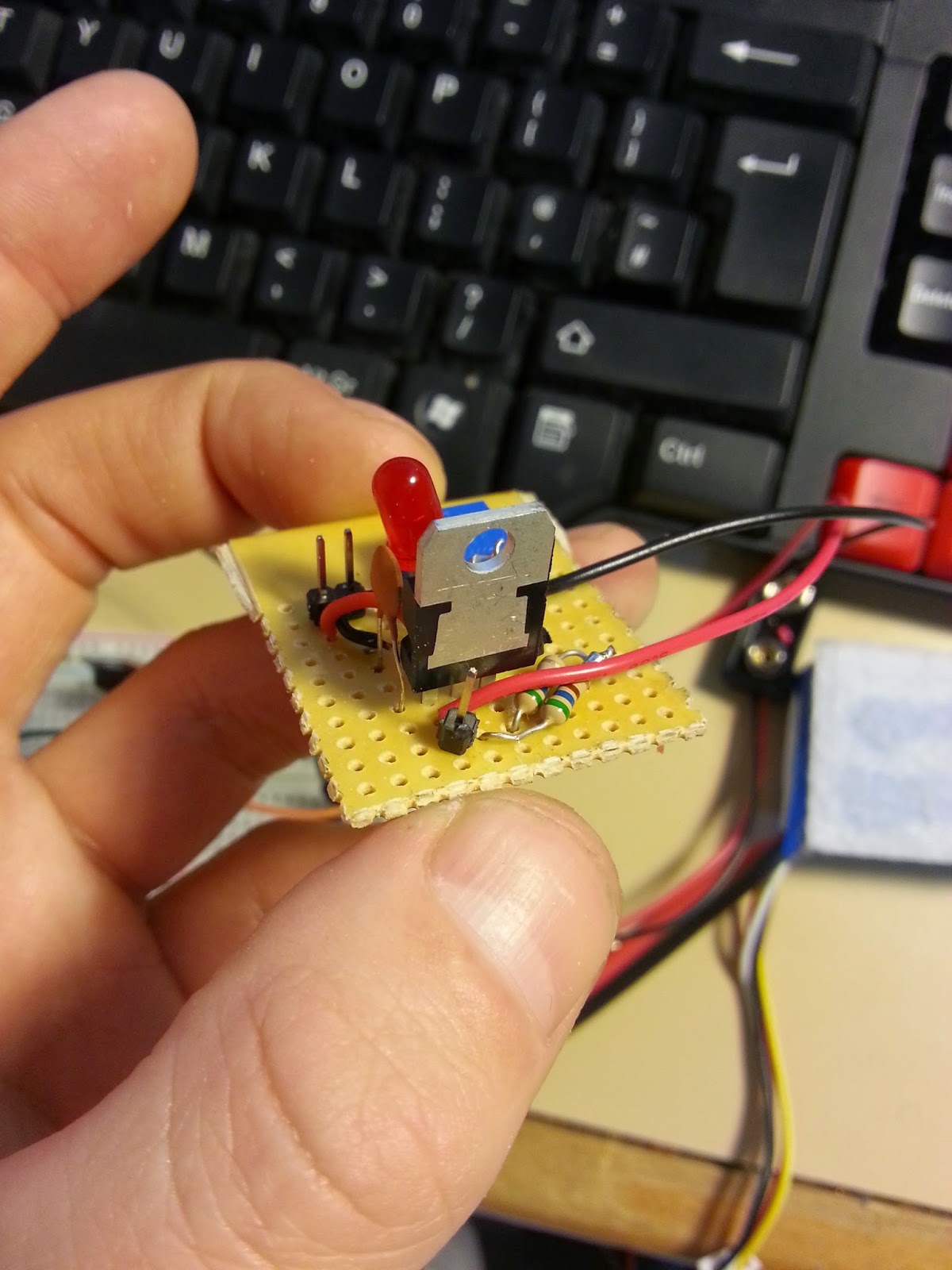
  • Red LED- power
  • Blue LED- status
Note it has been said that the last 4 pins must be attached to VCC, however Great Scott the youtuber has had success with only the CH_PD attached to VCC.


Firmware

Needed a ttl to usb adaptor very cheap 1-2 pounds- i prefer the cable as its easier to work with. 

Following this tutorial (and for updating the firmware this great Video from Kevin Darrah- check his channel out!) i will update the firmware using a USB - TTL cable, i'm powering the ESP with the arduinos 3.3v and ground although the arduino wont give the max current the ESP will take it will be enough for updating the firmware (just a bit slower). the green TX of the TTL cable goes to the RX of the ESP and the white RX of the TTL to the TX of the ESP.

Flash mode pin config

The other side of the cable im holding is USB and goes to ...the computer.
Im only using the power form the arduino here.
Note the shared ground. 


  • VCC- 3.3 from arduino
  • GND- from arduino also shared with the TTL cable
  • RX- connects to TX of TTL (green)
  • TX- connects to RX of TTL (white)
  • GPIO 0- set LOW
  • GPIO 2- set HIGH
  • GPIO 15- set LOW OR HIGH?! (SDM model)
  • RST- reset HIGH 
  • CH_PD-  HIGH


  • When the ESP is connected up- with power then connect to the computer. Before flashing with the software on the tutorial, make sure that you have updated the driver for the usb cable, goto devices and printers and auto update the driver. Now you should be able to flash the device.

    Follow the video and blog!

    And Then?

    if you have followed the tutorial, and have flashed the chip with new firm ware, we can now test it. Open the arduino IDE and select the com port that your ttl cable is connected to, open the serial monitor and try some commands.

    Some chips are already set to work at 9600 baud rate mine was, if not you might have to try 
    115200 and possibly others. Set auto scroll and "Both NL & CR"

    • AT
      • a simple test it should return "OK"
    • AT+RST
      • resets the board returns "[System Ready, Vendor:www.ai-thinker.com]" could fscanf or read for this line to ensure it has been restarted. (changed from firmware version to version)
    • AT+GMR
      • tells you the firmware its running
    • AT+CWMODE=?
      • tells you what modes it will accept: can be..
      • a device on the network
      • an access point- can log into it setup a password and ssid (completely stand alone device)
      • both
    • AT+CWMODE=1
      • changes mode 1-3
    • AT+CWMODE?
      • current mode
    • AT+CWLAP
      • displays wifi points
    • AT+CWJAP="SSID wifi name","password"  
      • connects to WIFI
    • AT+CWJAP?
      • check to see if connected to WIFI
    • AT+CIPMUX=1
      • setting it to accept multiple connections, required for the tcp connection to the internet.
      • Must always set the every time device is powered down!!!
    • AT+CIPMUX?
      • current mode
    • AT+CIPMODE=0
      • not data mode (= 1 is possible to set data streaming mode)


    And Then?

    So now we can connect to a wifi network and set the ESP to different modes.

    In my next post i'm going to have examples of getting data from the internet using the last two links under useful Reference Material. Here for a video

    Useful Reference Material

    Youtube

    Kevin Darrah- Just go there!
    Great Scott!- Lots of links in the info box (under the video)
    Julian Llett- Alot of interesting videos, lots of iot stuff
    AllAboutEE- Same as above

    Yahoo Query Language-
    Yahoo Query Language tutorial-

    Friday 17 April 2015

    8x8 Led Matrix using Max7219 IC


    The Board

    The Maxim 7219 IC

    Info here

    The Library (LedControl)

    info here

    The Code


    Notes

    Can be daisy chained..

    setup functions

    void setup()
    {
      lc.shutdown(0,false);  // Wake up displays

      lc.setIntensity(0,1);  // Set intensity levels 1-15

      lc.clearDisplay(0);  // Clear Displays
    }

    lighting individual leds

    /* 
     * Set the status of a single Led.
     * Params :
     * addr  address of the display 
     * row   the row of the Led (0..7)
     * col   the column of the Led (0..7)
     * state If true the led is switched on, 
     * if false it is switched off
     */
    void setLed(int addr, int row, int col, boolean state);

    example
    //switch on the led in the 3'rd row 8'th column
    //and remember that indices start at 0! 
    lc.setLed(0,2,7,true);   
    //Led at row 0 second from left too
    lc.setLed(0,0,1,true);   
    delay(500);
    //switch the first Led off (second one stays on)
    lc.setLed(0,2,7,false);


    Control all leds in a row

    The setRow(addr,row,value)-function takes 3 arguments. The first one is the already familiar address of our device. The second one is the row that is going to be updated and the third one the value for this row.

    Here is the signature of the method :

    /* 
     * Set all 8 Led's in a row to a new state
     * Params:
     * addr  address of the display
     * row   row which is to be set (0..7)
     * value each bit set to 1 will light up the corresponding Led.
     */
    void setRow(int addr, int row, byte value);

    example
    //include this file so we can write down a byte in binary encoding
    #include <binary.h>

    //now setting the leds from the third row on the first device is easy
    lc.setRow(0,2,B10110000);

    Ref websites 

    http://playground.arduino.cc/Main/LedControl
    https://brainy-bits.com/tutorials/how-to-control-max7219-led-matrix/


    Thursday 22 January 2015

    Adjustable DC voltage using Lm317

    Intro

    I need a separate supply to drive servos for a robot arm i'm building. i'm using a 10k potentiometer and in the examples they use 5k, i found with the 10k potentiometer the voltage would only change in the lower 1/4 of the potentiometer (hard to select a particular voltage). I swapped out the 220 Ohm resistor recommended and used two 500 ohm resistors in series, now the whole of the potentiometer varies the output voltage.

    Useful examples
    http://www.circuitsgallery.com/2012/11/variable-power-supply-circuit.html
    http://www.eleccircuit.com/my-first-variable-dc-power-supply-1-2v-to-30v-1a-by-lm317/

    Data Sheet
    https://www.fairchildsemi.com/datasheets/LM/LM317.pdf


    headers are for Vin and Vout
    two resistors in series


    Thursday 2 October 2014

    Light Following Robot

    Light Following Robot Using 555 Timers.


    I actually made this towards the end of March, i became interested in using integrated circuit and micro chips to make stand alone projects as they are cheaper than using an arduino for each project.

    There are two configurations for 555 timers mono stable and astable. For this project monostable is used. A great website explaining how they work.


    Monostable Operation

    "Unlike the astable, which has two unstable states and so continually switches from one to the other and back again, the monstable has one stable state and one unstable state.
    When triggered by a suitable pulse at its input (pin 2) it switches from its stable state, in which the output is low, to its unstable state where its output is high. This state exists for a time controlled by the values of R1 and C1, and at the end of this period the output switches back to its stable (low) state. Its primary use is therefore to produce a set time delay, initiated by an input pulse."


    Quote and image taken from http://www.learnabout-electronics.org/

    Building The LFR

    I followed this instructables it was the most simple one i could find, there are other tutorials out there that use potentiometers to set the sensitivity of the LDR's and hence the speed of the motors.


    Conclusion

    The idea worked however the LFR didnt really move.. i didnt have proper wheels, i cut some out from cardboard. Also the fact i didn't use motors with gear boxes and gave the motors more voltage than they needed resulted in not much torque.

    For my first play with 555 timers i am still happy with the out come. Ultimately i decided that having a mobile platform that i could add sensors to and program would be a better use of my time and didn't continue with it.

    Sunday 21 September 2014

    433Mhz RF Transmitter and Receiver

    433Mhz RF Transmitter and Receiver.


    I wanted a cheap wireless solution, these are great at little over a pound each. 
    This is a great instructables on them with all the specs. Limitations are that they easily loose connection with each other, and don't really have enough power to go through more than one wall (on 5v) a max range of 100 M can be achieved with LOS (line of sight) also the direction of the antenna greatly affects performance.


    Virtual Wire

    The VirtualWire library allows you to easily communicate over RF. Official VirtualWire Documentation (PDF).


    Test project

    I wanted to control a coffee machine using these the idea was to have a button on my desk with an RGB LED, off: the LED would pulse red, brewing: the led would stay yellow and ready: the LED would pulse green.

    First prototype: got the led to work correctly with me pushing the button it would cycle through the colors no problem.

    Second prototype: Modified the example Tx and Rx code from virtual wire library to send a 1 then 0 with a second gap in between. added relay to control coffee machine. 

    Third prototype: combined both codes into one found that the LED wasn't working as expected it wouldn't display certain colors and i reasoned it was because the Tx part of the code being constantly sent with a small delay- this delay affected the PWM of the LED. To make it work a micro controller able to run two sets of code at the same time would be needed. But this expense is a little overkill for a simple remote coffee machine.

    Forth prototype: i simplified the user experience to a simple on/off, green/red operation.
    however the leds flash briefly, assume this is when data is being Tx.

    Im not going to use these to remotely control my coffee machine as the connection is unreliable and unable to reach the distance to it. I'm going to test these and see if i have better luck, also i need a way of getting 5-12 V from the mains to power the Rx. 


    Hardware Connections

    Rx Signal Wire to D12

    Tx Signal Wire to D12


    Code

    As i was only sending 1 or 0 i changed the following line in the set up. This is an array that holds the data you want to Tx.

    char Sensor1CharMsg[2];

    This line converts an integer array to a character array.

     itoa(ButtonData,ButtonCharMsg,10);
     
    Great information on converting CHAR to INT and vice versa.

    Tuesday 3 June 2014

    Writing A Class

    Writing A Class In Processing

    As I'm not a programmer my understanding of the lingo needs improving I decided to investigate it. This tutorial by Daniel Shiffman (lots of good stuff on his website) helped me understand how they work.

    Get to the chopper!

    So me and a friend Micheal were drinking a few in my room and he suggested we make an app that when the button is pressed a random jpeg is displayed along with an mp3- we didn't get that far, but the next day i looked over it and decided to make it work but i would use classes.

    Say cheese!

    The Arnold app

    All the libraries i used should be included with processing. A problem i couldn't work out is that i wanted to be able to be a bit "trigger happy" with the mouse button, So that if the user didn't like the mp3 being played they could simply click and a new picture and mp3 would be played. I couldn't figure it out and we think its something to do with having one audio player object, having more would overkill for a small app. The solution would be to find a new library with better features and use something "better" like Python.

    Multiple Serial Ports

    Exploring Multiple Serial Ports Using Arduino Mega.


    I searched around for this because i will need to use it in future projects, at the moment i'm gearing up to build a mobile platform- wouldn't it be nice if it could map a room using sonar data... Anyway i found this excellent blog that explains it nearly perfectly apart from the TX to RX bit in step one, just beware, if you don't know what i'm on about I've made a comment at the bottom of his post.

    Using a USB to serial TTL cable allows another serial port to be connected to a PC from the mega. 

    USB To TTL Cable 

    The mega has 4 possible ports to utilize. The green is TX and should be connected to RX on the board the white is RX and should be connected to TX on the board, red is power and is optional (5V external) and black is ground. the USB is simply connected to a port on the PC.

    Ive put together a sketch that reads an LDR and prints the value to one serial port whilst the other port is used to keep track of when an led (the on board one connected to pin 13) is turned on and off using a button.

    Resistors 10K (theres one behind the LDR)

    To view two serial monitors in the arduino IDE open a fresh arduino program and set that to the serial port of your cable, or use Tera Term.

    Com7 Showing LDR Values Com9 showing that switch is off